How to Build a DIY Thermal Camera: A Beginner’s Guide
Wondering how to create a thermal camera on your own? With just a few core components like a thermal sensor, a microcontroller, a display, and a battery, you can build a basic device to visualize heat.
Once you assemble and calibrate it, you’ll be able to see thermal data in real time.
Keep reading to get the full step-by-step guide.
What Are the Core Components You’ll Need?
The core components you’ll need include an infrared sensor module, such as the MLX90640 or FLIR Lepton, which captures thermal data with high accuracy. You’ll pair this sensor with a microcontroller like a Raspberry Pi or ESP32 to handle data processing and control functions. For displaying the thermal images, a 7-inch LED or OLED screen works well, providing clear visualization. Power is critical for portability; a 3.7V lithium-polymer (LiPo) battery combined with a boost converter ensures stable voltage supply while maximizing runtime. The SPI bus is used for video data transmission from the sensor to your microcontroller. To protect and organize your setup, you’ll house everything inside a sturdy enclosure, secured with mounting hardware like M3 screws. Additionally, incorporating a calibration shutter mechanism is essential for sensor calibration, which ensures precise and reliable temperature readings. Understanding the difference between thermal imaging and night vision can help you appreciate your camera’s unique capability to detect heat signatures, while a comparison of performance versus cost may influence your component choices. Choosing a simple project case can offer significant cost savings without sacrificing functionality.

[MLX90640ESF 32X24 SENSOR MODULE] This listing is for MLX90640ESF 32x24 infrared for temperature array module with a built-in microcontroller that outputs 768 for temperature data points over serial/USB and works with supplied PC software for thermal graph display.

How to Choose the Right Thermal Sensor for Your Project?
To select the right thermal sensor for your project, start by determining the required temperature range and resolution. For detailed thermal mapping, sensors like the MLX90640, with a range of -40 to 300°C and 0.1°C resolution, are suitable due to their high pixel count of 768. If your application demands higher accuracy within a narrower range, consider sensors like the TMP117, which offers an accuracy of ±0.1°C.
Next, ensure the sensor can operate reliably under your ambient conditions. Many thermal sensors function effectively from -50°C to 700°C, but verifying this range is crucial to prevent inaccuracies or sensor failure. For field use, also consider the durability of the final assembly, as many commercial thermal camera models survive drops from 2 meters. Finally, match the sensor’s interface and output type with your project’s requirements—whether it’s an analog signal, digital communication, or integrated calibration—and confirm it can perform stably within your specific environmental and electrical conditions.

WIDE COMPATIBILITY: Designed for Raspberry Pi, Arduino, STM32, and other MCUs. Features I2C communication (up to 1MHz), compatible with 3.3V/5V systems

Adopts MLX90640 far-infrared thermal sensor array, 32×24 pixels

High-Accuracy Thermal Sensor – Features a 32x24 IR array with ±2℃ precision, ideal for HVAC systems and fire detection applications.
Selecting a Microcontroller and Power Supply
Choosing the right microcontroller and power supply is essential for reliable operation. A common choice for sensors that use I2C communication is the ESP32, which natively supports this protocol, making integration straightforward. For this DIY thermal camera, the ESP32 SoC is used for control and processing. If you need to prioritize low power consumption, especially for portable or battery-powered units, the STM32 series is an excellent option because of its energy-efficient features. A thermal imager works by detecting infrared radiation and converting it into an electronic signal.
For powering your system, most sensors and microcontrollers operate at 3.3V logic levels. To convert from a higher voltage source, like 5V USB power, you should include a regulator such as the MIC5219. When selecting batteries, an 18650 Li-ion cell offers good capacity and rechargeability, especially when paired with a TP4056 charger module for consistent, safe charging. An infrared illuminator can be a critical accessory if you need to image in total darkness, as it floods the area with invisible infrared light that the sensor can detect. Assembling the drone will also require other specialized thermal drone tools beyond just the electronics.
It’s crucial to account for voltage drops across regulators and ensure your battery capacity matches your sensor’s sampling frequency. This consideration guarantees several hours of continuous operation without interruptions. Proper power management and regulation are key to maintaining stable readings and preventing system resets caused by voltage fluctuations.

Entering download mode: Press and hold the BOOT button of ESP32C3, then press the RESET button, release the RESET button, and then release the BOOT button, at this time, ESP32C3 will enter the download mode. (You need to re-enter the download mode every time you connect, sometimes you press it once, the port is unstable and will disconnect, you can judge it by the port recognition sound)

The expansion board is equipped with a DC power connector that supports 6.5V–9V DC input and features an integrated on-board voltage regulator circuit. When a project requires driving multiple peripherals, the system can be powered directly from an external power supply, providing stable power support.

2.4GHz Dual Mode WiFi + Bluetooth Development Board
Picking a Display for Your Thermal Camera
A 320×240 pixel display provides a solid baseline for clarity when visualizing thermal data from sensors like the MLX90640. For more detailed thermal gradients, consider screens with 480×272 or 640×480 resolutions. The display size affects portability; screens ranging from 2.8 inches to 3.5 inches are common choices that balance visibility with compactness. This level of detail is crucial for distinguishing thermal signatures in the field, based on the principle that different materials emit varying amounts of infrared radiation.
Selecting the right display type is crucial for outdoor or high-brightness environments. High-brightness panels (500+ nits) improve outdoor visibility, especially under direct sunlight, and an anti-glare coating can further enhance readability. IPS screens offer wider viewing angles and consistent color accuracy, making them suitable for collaborative or field work. Touch capability adds an interactive element, allowing you to control and manipulate thermal images directly on the display. This is a distinct advantage over the fixed green monochrome displays used in many night vision systems.

HIGH-DEF IPS VISUALS: View for crisp 320x480 images with rich colors from any angle on this 3.5 Inch IPS LCD Display for clear project monitoring

𝗗𝗶𝗿𝗲𝗰𝘁𝗶𝗼𝗻 𝗠𝗶𝘅𝗲𝗱 𝗖𝗼𝗻𝘁𝗿𝗼𝗹:20 groups of model names can be named, and all switch knob buttons can be assigned to control channels.Users can operate climbing vehicles, crawler vehicles and any two channels for mixing control more easily,you can also use it to control model cars, model boats, robots, etc.

【Highly 】: Designed with longevity in mind, our lcd screen inside pc case is housed in an ABS material. Exceptionally to wear, this device promises a long service time of optimal performance.
A Step-by-Step Guide to Assembly and Wiring
To assemble your thermal camera’s core electronic components, follow these precise steps. Start by soldering the 24-pin and 5-pin header strips onto your AMG8833 or MLX90640 sensor. Ensure the headers are perpendicular to the sensor board to establish reliable connections. Next, connect the sensor to your Arduino Nano: link VCC to 3.3V, GND to ground, SDA to A4, and SCL to A5. Mount the germanium lens in front of the sensor for optimal thermal imaging, which works because germanium is transparent to long-wave infrared radiation. For your project, consider the benefits of building a thermal monocular to understand the full scope of components and applications. Before proceeding, gather all necessary tools and parts as outlined in a comprehensive DIY guide. For power management, connect your TFT display’s VCC to the Nano’s 5V pin and GND to ground, then wire SCK to digital pin 13. Confirm all connections are secure to prevent calibration issues later. Finally, attach your battery, with the red wire connecting to the positive terminal and the black wire to the negative terminal, ensuring proper power flow. Double-check each connection before powering up to avoid damage and ensure calibration accuracy.

AMG8833: next generation of 8x8 thermal IR sensors from Panasonic

AMG8833 of 8x8 thermal IR sensor, returns an array of 64 individual infrared temperature readings over I2C (default address 0x69, optional 0x68)

Electronics/Computers/Accessories/Computer Components/Single Board Computers
Installing Software and Uploading Code
To get your thermal camera working, you’ll need to install the software and upload the code to your microcontroller. Begin by flashing Raspbian Bullseye onto your SD card, which provides a stable operating system optimized for Raspberry Pi devices. After inserting the SD card into your Pi, boot it up and update the system packages with commands like `sudo apt update` and `sudo apt upgrade` to ensure all software is current.
Next, install essential build tools such as `cmake` and `git` using `sudo apt install cmake git`. Enabling the I2C interface is crucial for sensor communication; use `raspi-config` to activate I2C and then adjust its baud rate for optimal data transfer. Verifying the connection with `i2cdetect -y 1` to confirm the sensor’s detection is a key step in ensuring your underlying technology is functioning correctly.
For Python dependencies, create a dedicated virtual environment with `python3 -m venv env`, activate it using `source env/bin/activate`, and install needed libraries like `opencv-python` and `adafruit-circuitpython-mlx90640` with `pip`. This setup isolates project-specific packages and avoids conflicts. Gathering the required tools and parts before you begin will streamline the entire build process.
Download the Project Bundle, which contains your code files, and place `code.py` directly into your home directory or desired location. Edit the autorun script—often named `.profile` or `rc.local`—to execute `python3 ~/code.py` during startup, ensuring your camera runs automatically. Finally, execute the main script manually to verify functionality and run `i2cdetect` again to ensure the sensor is properly recognized and communicating correctly. Remember, while a DIY thermal camera can be built, standard iPhone models lack a true thermal imaging sensor.
How to Test, Calibrate, and Verify Accuracy
To verify your thermal camera’s performance, begin with calibration techniques using known reference sources. For a 0°C point, immerse a well-stirred ice bath and set the camera’s emissivity to 0.95. For a 100°C reference, use boiling water and adjust for altitude to account for the slight variations in boiling point. These DIY calibration steps establish a baseline that you can rely on for general measurements, with consumer-grade accuracy typically within plus or minus 2°C.
Next, check for image uniformity across the sensor. This involves capturing images of a uniform temperature source, like a flat black surface or a thermal calibration plate, to identify any irregularities or dead pixels. Uniform images indicate the sensor responds consistently across all pixels.
Sensor response should also be verified by measuring a known temperature at multiple points, ensuring the camera provides accurate and calibrated readings. If available, use professional-grade tools like blackbody simulators, which are blackbody sources that produce precise, stable thermal emissions. These provide the most reliable reference points for calibration and verification.
Finally, test the geometric accuracy by measuring known objects at specific distances and comparing the camera’s measurements against their actual dimensions. This ensures the system’s spatial readings are trustworthy and helps calibrate any distortions or misalignments in the camera’s optics.
Troubleshooting Common Thermal Camera Issues
If your thermal camera starts acting up, you’ll typically encounter problems related to power, image quality, hardware, or software. Begin by inspecting the battery thoroughly. Look for swelling, corrosion, or damage to contacts, and ensure the polarity is correct during replacement. Clean the contacts gently to ensure a good connection. If problems persist, perform a hard reset to restore the device to its default settings.
For unclear images, first check that your palette mode and temperature range settings are appropriate for the scene. Recalibrate the sensor using a known reference target to improve accuracy. Be mindful of environmental factors such as high humidity, extreme heat, or cold, which can distort readings. Ensure the lens is spotless and that ventilation openings are free of dust or debris to prevent overheating. Additionally, observe the camera’s temperature scale adjustments to ensure it is not auto-ranging to an extreme that obscures the details you need to see.
Verify all cable connections, making sure they are securely attached. Damaged power buttons or software malfunctions might require a firmware update or hardware replacement. Regular maintenance and careful handling can prevent many common issues.
Processing Thermal Images and Building a User Interface
Once you’ve collected raw thermal sensor data, the next step is to convert it into a usable thermal image. Start with thermal calibration: adjust the raw data to correct for sensor noise and inaccuracies by applying a calibration curve or tuning parameters specific to your sensor. This process ensures that each pixel value accurately reflects temperature differences.
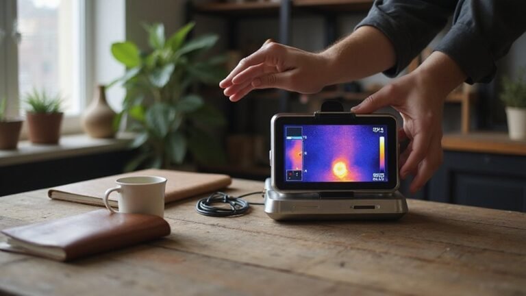
After calibration, transpose the image matrix to match the correct orientation. Assign a color palette where warmer temperatures are represented by reds and cooler ones by darker shades or grayscale. This mapping helps users intuitively interpret thermal variations. Use consistent color palettes across image sets to maintain accuracy and facilitate comparison.
For visualization, generate a color mosaic or grayscale image displayed in a user-friendly interface. Include tools that let users select specific thermal bands, which is useful if your sensor captures multiple spectral ranges. Incorporate toggles for point cloud views to visualize data in three dimensions, and add options to create index maps, such as thermal indices that highlight particular features. For analysis in external GIS tools, orthomosaics can be exported in formats like 8-bit pseudo-elevation for detailed inspection.
Ensure your processing workflow discards blurry images by implementing sharpness or focus assessments. Maintain consistent color mapping throughout sessions to provide reliable visual analysis. By following this workflow, you transform raw thermal data into clear, accurate images and an interactive interface capable of advanced thermal analysis.